Construction of the gas storage system
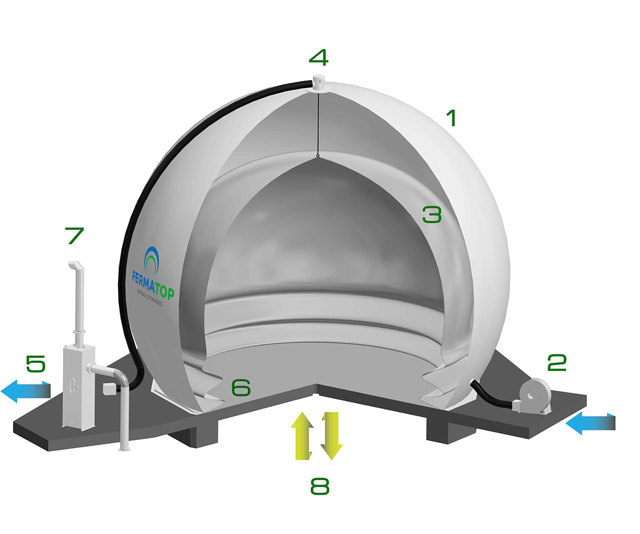
The air-supported outer membrane (1) works as the weather protection roof, and fulfills the local needs for wind- and snowload by choosing the matching blower pressure.
The radial blower (2) also gives the necessary pressure to operate the plant.
The inner membrane (3) represents the variable gas space.If more biogas will be supplied than consumed, the inner membrane will be filled steady.
The level sensor (4) analogously gives a 4-20 mA output signal to the plants PLC.
The air between the membranes escapes through the outlet-side pressure flap (5), which allows to further fine-tune the pressure.
Once gas is consumed, the volume and the height of the inner membrane will be reduced again.
Easily maintainable anchoring profiles (6) attach the gas storage to the ground.
Reliable hydraulic safety valves are used as overpressure/vacuum protection (7).
Gas inlet and outlet supplied by gaspipes built into concrete foundation (8).

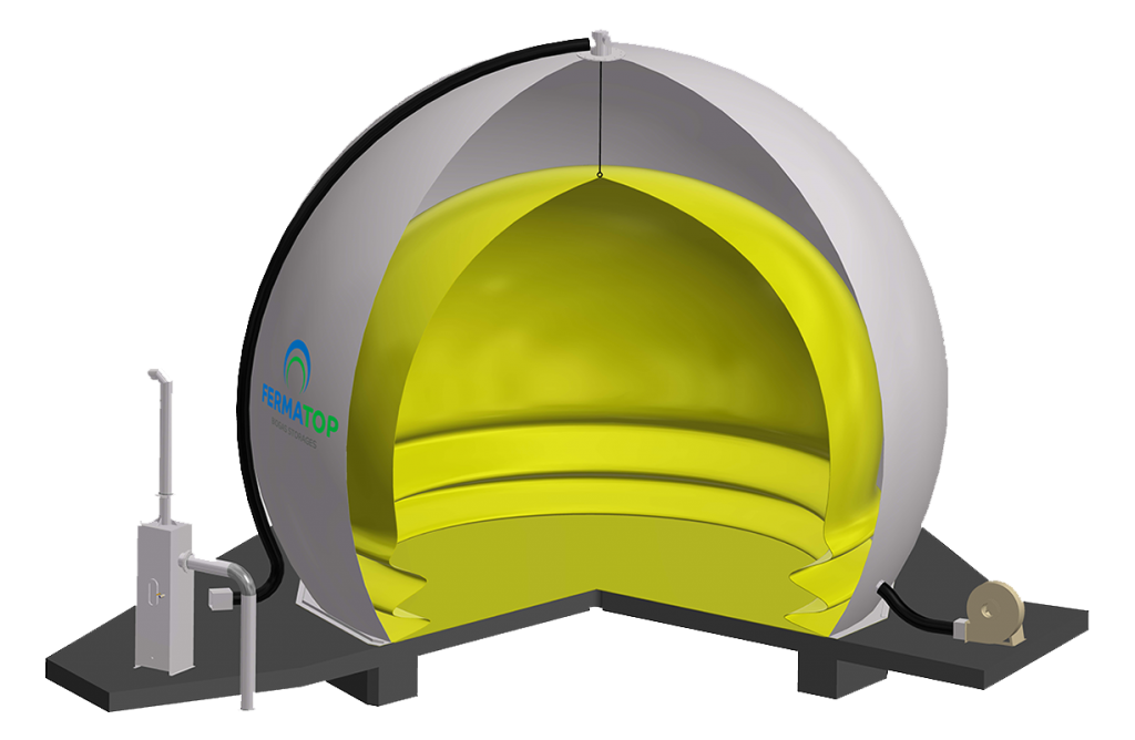
Gasholder on basement
Usually, the standard gasholder is mounted on a foundation plate (concrete, steel, etc.). The seal to the ground is made via an additional base membrane.
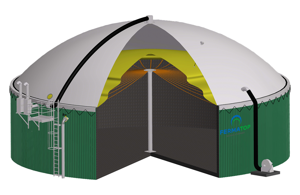
Gasholder installed on tank
The top mounted storage tank is installed on concrete or steel tanks. A central mast combined with straps prevents the inner membrane from touching sludge or mixers at low gas levels.


Single membrane roof
At plants (without gas storage) which only need a roof for weather-protection and emission reduction.
Gasbag
The most economical solution of storing gas is by using single membrane gasbags.
They are available in different shapes and sizes. Typically, gasbags have a cylindric body and spherical shaped ends. The gasbag can be installed horizontally or vertically.


